|
Entries tagged arduino
31 December 2016 21:50
Since I've got a few weeks off I've decided I need to find a project, or
two, to occupy me. Happily the baby is settling in well, mostly he
sleeps for 4-5 hours, then eats, before the cycle repeats. It could
have been so much worse.
My plan is to start exploring Arduino-related projects. It has been years
since I touched hardware, with the exception of building a new PC for myself
every 12-48 months.
There are a few "starter kits" you can buy, consisting of a board, and some discrete components such as a bunch of buttons, an LCD-output screen, some sensors (pressure, water, tilt), etc.
There are also some nifty little pre-cooked components you can buy such as:
The appeal of the former is that I can get the hang of marrying hardware
with software, and the appeal of the latter is that the whole thing is
pre-built, so I don't need to worry about anything complex. Looking
over similar
builds people
have made, the process is more akin to building with Lego than real hardware-assembling.
So, for the next few weeks my plan is to :
- Explore the various sensors, and tutorials, via the starter-kit.
- Wire the MP3-playback device to a wireless D1-mini-board.
- Which will allow me to listen to (static) music stored on an SD-card.
- And sending "next", "previous", "play", "volume-up", etc, via a mobile.
The end result should be that I will be able to listen to music in my
living room. Albeit in a constrained fashion (if I want to change the
music I'll have to swap out the files on the SD-card). But it's
something that's vaguely useful, and something that I think is within my
capability, even as a beginner.
I'm actually not sure what else I could usefully do, but I figured I could probably wire up a vibration sensor to another wireless board. The device can sit on the top of my washing machine:
- If vibration is sensed move into the "washing is on" state.
- If vibration stops after a few minutes move into the "washing machine done" state.
- Send a HTTP GET-request, which will trigger an SMS/similar.
There's probably more to it than that, but I expect that a simple
vibration sensor will be sufficient to allow me to get an alert of some
kind when the washing machine is ready to be emptied - and I don't need to poke inside the guts of the washing machine, nor hang reed-switches off the door, etc.
Anyway the only downside to my plan is that no doubt shipping the toys from AliExpress will take 2-4 weeks. Oops.
Tags: arduino
|
28 January 2017 21:50
At the end of December I decided I was going to do hardware "things", and so far that has worked out pretty well.
One of the reasons I decided to play with Arduinos is that I assumed I could avoid all forms of soldering. I've done soldering often enough to know I can manage it, but not quite often enough that I feel comfortable doing so.
Unfortunately soldering has become a part of my life once again, as too many of the things I've been playing with have required pins soldering to them before I can connect them.
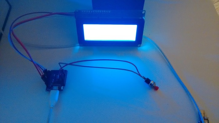
Soldering aside I've been having fun, and I have deployed several "real" projects in and around my flat. Perhaps the most interesting project shows the arrival time of the next tram to arrive at the end of my street:
That's simple, reliable, and useful. I have another project which needs to be documented which combineds a WeMos D1 and a vibration sensor - no sniggers - to generate an alert when the washing machine is done. Having a newborn baby around the place means that we have a lot of laundry to manage, and we keep forgetting that we've turned the washing machine on. Oops.
Anyway. Hardware. More fun than I expected. I've even started ordering more components for bigger projects.
I'll continue to document the various projects online, mostly to make sure I remember the basics:
Tags: arduino, esp8266
|
2 February 2017 21:50
The past few days I've been doing more arduino-work. In between dying of sleep-exhaustion.
One thing that always annoyed me was that I had to hard-code my WiFi credentials in my projects, with code like this:
//
// Connect to the SCOTLAND network
//
WiFi.mode(WIFI_STA);
WiFi.hostname("tram-clock");
WiFi.begin("SCOTLAND", "highlander1");

//
// Attempt to connect - TODO: Timeout on failure
//
while (WiFi.status() != WL_CONNECTED)
    delay(500);

//
// Now we're connected show the local IP address.
//
lcd.print("WiFi connected  ");
lcd.print(WiFi.localIP());
Whilst looking at another project I found a great solution though. There is a library called WiFiManager which behaves perfectly:
- If you've stored connection details it will connect to the local WiFI network using those, automatically.
- If you've not saved previous connection details it will instead configure the device to work as an Access Point
- You can then connect to that access point and see a list of local WiFi networks.
- Choose the appropriate one from the list, enter your password, and these details are saved for the future.
- The device will then reset, join the network via your saved choices and acquire an IP via DHCP as you'd expect.
The code for this is beautifully simple:
//
// Connect to WiFI with saved credentials, if any.
//
// Otherwise work as an access-point, named TRAM-TIMES, and
// let the user fill out their details.
//
WiFiManager wifiManager;
wifiManager.autoConnect("TRAM-TIMES");
This means my current project, which continues to revolve around tram-times, is so very much more user-friendly. It is a product you could package and take to a friends house, not a project you have to recompile to tweak.
For that reason, user-niceness, I reworked the on-board HTTP status-page to use bootstrap, be themed, and look nicer. Other than being housed in a horrid case the project actually looks like a product. Not one I'd buy, but neither one I'm ashamed of sharing.
Tags: arduino, esp8266
|
20 April 2017 21:50
I've heard about 3d-printing a lot in the past, although the hype seems to have mostly died down. My view has always been "That seems cool", coupled with "Everybody says making the models is very hard", and "the process itself is fiddly & time-consuming".
I've been sporadically working on a project for a few months now which displays tram-departure times, this is part of my drive to "hardware" things with Arduino/ESP8266 devices . Most visitors to our flat have commented on it, at least once, and over time it has become gradually more and more user-friendly. Initially it was just a toy-project for myself, so everything was hard-coded in the source but over time that changed - which I mentioned here, (specifically the Access-point setup):
- When it boots up, unconfigured, it starts as an access-point.
- So you can connect and configure the WiFi network it should join.
- Once it's up and running you can point a web-browser at it.
- This lets you toggle the backlight, change the timezone, and the tram-stop.
- These values are persisted to flash so reboots will remember everything.
I've now wired up an input-button to the device too, experimenting with the different ways that a single button can carry out multiple actions:
- Press & release - toggle the backlight.
- Press & release twice - a double-click if you like - show a message.
- Press, hold for 1 second, then release - re-sync the date/time & tram-data.
Anyway the software is neat, and I can't think of anything obvious to change. So lets move onto the real topic of this post: 3D Printing.
I randomly remembered that I'd heard about an online site holding 3D-models, and on a whim I searched for "4x20 LCD". That lead me to this design, which is exactly what I was looking for. Just like open-source software we're now living in a world where you can get open-source hardware! How cool is that?
I had to trust the dimensions of the model, and obviously I was going to mount my new button into the box, rather than the knob shown. But having a model was great. I could download it, for free, and I could view it online at viewstl.com.
But with a model obtained the next step was getting it printed. I found a bunch of commercial companies, here in Europe, who would print a model, and ship it to me, but when I uploaded the model they priced it at €90+. Too much. I'd almost lost interest when I stumbled across a site which provides a gateway into a series of individual/companies who will print things for you, on-demand: 3dhubs.
Once again I uploaded my model, and this time I was able to select a guy in the same city as me. He printed my model for 1/3-1/4 of the price of the companies I'd found, and sent me fun pictures of the object while it was in the process of being printed.
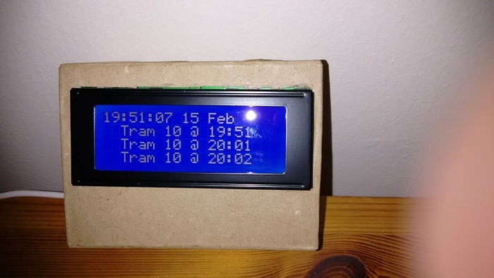
To recap I started like this:
Then I boxed it in cardboard which looked better than nothing, but still not terribly great:
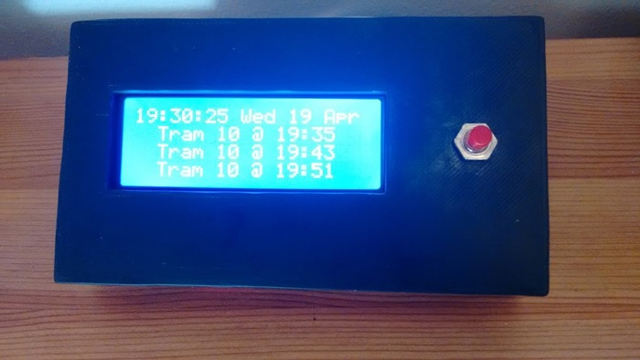
Now I've found an online case-design for free, got it printed cheaply by a volunteer (feels like the wrong word, after-all I did pay him), and I have something which look significantly more professional:
Inside it looks as neat as you would expect:
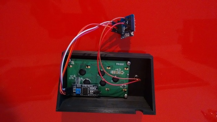
Of course the case still cost 5 times as much as the actual hardware involved (button: €0.05, processor-board €2.00 and LCD I2C display €3.00). But I've gone from being somebody who had zero experience with hardware-based projects 4 months ago, to somebody who has built a project which is functional and "pretty".
The internet really is a glorious thing. Using it for learning, and coding is good, using it for building actual physical parts too? That's something I never could have predicted a few years ago and I can see myself doing it more in the future.
Sure the case is a little rough around the edges, but I suspect it is now only a matter of time until I learn how to design my own models. An obvious extension is to add a status-LED above the switch, for example. How hard can it be to add a new hole to a model? (Hell I could just drill it!)
Tags: 3d-printing, arduino, esp8266
|
6 June 2019 12:01
Recently I wanted to monitor the temperature and humidity of a sauna. I figured the safest way to go would be to place a battery-powered temperature/humidity sensor on a shelf, the kind of sensor that is commonly available on AliExpress for €1-5 each.
Most of the cheap "remote sensors" transmit their data over a short 433Mhz radio-transmission. So I just assumed it'd be possible to work something out.
The first step was to plug an SDR-dongle into my laptop, that worked just fine when testing, I could hear "stuff". But of course a Sauna is wood-lined, and beyond a tiled-shower area. In practice I just couldn't recieve the signal if my laptop lived in its usual location.
So I came up with a fall-back plan:
- Wire a 433Mhz receiver to an ESP8266 device.
- Sniff the radio-transmission.
- Decode it
- Inject into an MQ-host, via WiFi
Since the receiver could be within 10m of the transmitter I figured that would work fine - and it did. The real problem came when I tried to do this. There are a few projects you can find for acting as a 433Mhz -> WiFi bridge and none of them understood the transmission(s) my sensor was submitting.
In the end I had to listen for packets, work out the bit-spacing, and then later work out the actual contents of the packets. All by hand.
Anyway the end result is that I have something which will sniff the packets from the radio-transmitter, correctly calculate the temperature/humidity values and post them to MQ. From MQ a service polls the values and logs them to SQLite for later display. As a bonus I post to Slack the first time the temperature exceeds 50 °ree; a day:
- "Hot? It's like a sauna in here."
- "Main steam on, somebody set us up the beer."
- etc.
Next week I'll talk about how I had a similar (read: identical) problem reacting to the 433Mhz transmission triggered by a doorbell. None of the gateways I looked at logged a thing when the button was pressed. So I'll have to save the transmission via rtl_433, analyze it with audacity, and do the necessary.
For reference these are the three existing firmwares/solutions/projects I tried; on a Wemos Mini D1:
Tags: 433mhz, arduino, esp8266, radio, sdr
|
1 August 2019 13:01
This is part three in my slow journey towards creating a home-brew
Z80-based computer. My previous
post
demonstrated writing some simple code, and getting it running under an
emulator. It also described my planned approach:
- Hookup a Z80 processor to an Arduino Mega.
- Run code on the Arduino to emulate RAM reads/writes and I/O.
- Profit, via the learning process.
I expect I'll have to get my hands-dirty with a breadboard and naked
chips in the near future, but for the moment I decided to start with the
least effort. Erturk Kocalar has a website where he
sells "shields"
(read: expansion-boards) which contain a Z80, and which is designed to
plug into an Arduino Mega with no fuss. This is a simple design, I've
seen a bunch of people demonstrate how to wire up by hand, for example
this post.
Anyway I figured I'd order one of those, and get started on the easy-part, the software. There was some sample code available from Erturk, but it wasn't ideal from my point of view because it mixed driving the Z80 with doing "other stuff". So I abstracted the core code required to interface with the Z80 and packaged it as a simple library.
The end result is that I have a z80 retroshield library which uses an Arduino mega to drive a Z80 with something as simple as this:
#include <z80retroshield.h>


//
// Our program, as hex.
//
unsigned char rom[32] =
{
    0x3e, 0x48, 0xd3, 0x01, 0x3e, 0x65, 0xd3, 0x01, 0x3e, 0x6c, 0xd3, 0x01,
    0xd3, 0x01, 0x3e, 0x6f, 0xd3, 0x01, 0x3e, 0x0a, 0xd3, 0x01, 0xc3, 0x16,
    0x00
};


//
// Our helper-object
//
Z80RetroShield cpu;


//
// RAM I/O function handler.
//
char ram_read(int address)
{
    return (rom[address]) ;
}


// I/O function handler.
void io_write(int address, char byte)
{
    if (address == 1)
        Serial.write(byte);
}


// Setup routine: Called once.
void setup()
{
    Serial.begin(115200);


    //
    // Setup callbacks.
    //
    // We have to setup a RAM-read callback, otherwise the program
    // won't be fetched from RAM and executed.
    //
    cpu.set_ram_read(ram_read);

    //
    // Then we setup a callback to be executed every time an "out (x),y"
    // instruction is encountered.
    //
    cpu.set_io_write(io_write);

    //
    // Configured.
    //
    Serial.println("Z80 configured; launching program.");
}


//
// Loop function: Called forever.
//
void loop()
{
    // Step the CPU.
    cpu.Tick();
}
All the logic of the program is contained in the Arduino-sketch, and all
the use of pins/ram/IO is hidden away. As a recap the Z80 will make
requests for memory-contents, to fetch the instructions it wants to
execute. For general purpose input/output there are two instructions
that are used:
IN A, (1)   ; Read a character from STDIN, store in A-register.
OUT (1), A  ; Write the character in A-register to STDOUT
Here 1 is the I/O address, and this is an 8 bit number. At the moment
I've just configured the callback such that any write to I/O address 1
is dumped to the serial console.
Anyway I put together a couple of examples of increasing complexity, allowing me to prove that RAM read/writes work, and that I/O reads and writes work.
I guess the next part is where I jump in complexity:
- I need to wire a physical Z80 to a board.
- I need to wire a PROM to it.
- This will contain the program to be executed - hardcoded.
- I need to provide power, and a clock to make the processor tick.
With a bunch of LEDs I'll have a Z80-system running, but it'll be
isolated and hard to program. (Since I'll need to reflash the
RAM/ROM-chip).
The next step would be getting it hooked up to a serial-console of some
sort. And at that point I'll have a genuinely programmable standalone
Z80 system.
Tags: arduino, arduino mega, computer-building, github, gitlab, retroshield, z80
|
|
